Cómo configurar un patchbay en un estudio
¿Qué es un Patchbay?
Un patchbay actúa como un centro para conectar todos los componentes de su estudio, incluidos micrófonos, preamplificadores, efectos externos, mezcladores, auriculares o cualquier fuente o destino de audio en su sistema.
Antes de tener un patchbay, desconectaba y volvía a conectar constantemente los cables de las entradas y salidas de mi equipo. Pero ahora puedo dejar todo conectado al patchbay y simplemente usar un cable de conexión para hacer conexiones personalizadas según sea necesario. Esto me ahorra mucho tiempo de configuración, evita errores de parcheo que cuestan aún más tiempo y también protege mi equipo y cables del desgaste constante.
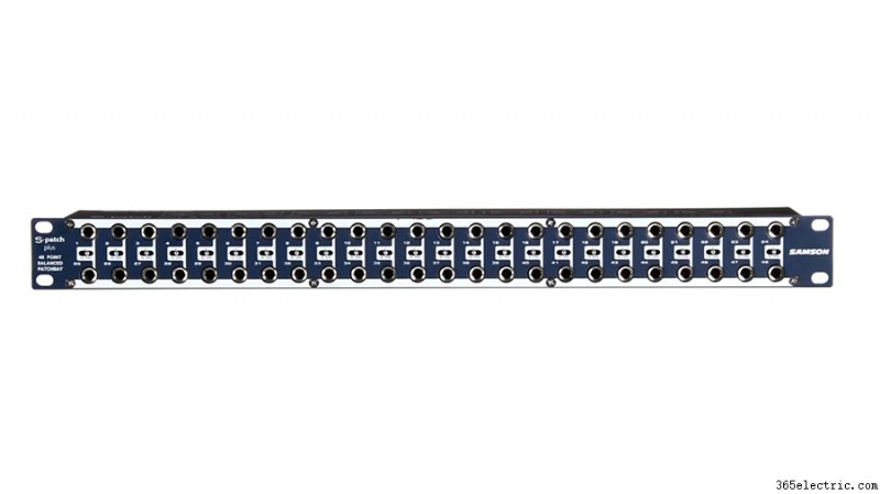
En la parte posterior de este patchbay TRS de ¼”, encontrará 24 conectores de entrada en la fila superior y 24 conectores de salida en la parte inferior. Esos 48 jacks en la parte posterior corresponden a los 48 jacks en el frente del patchbay. Por lo tanto, puede mantener todo su equipo enchufado en las tomas de la parte trasera y configurar flujos de señal personalizados conectando las tomas delanteras con cables de conexión.

Cómo configurar un Patchbay
Al configurar su patchbay, es importante pensar en el flujo de señal general de su estudio. De esa manera, puede diseñar su patchbay para que las funciones básicas de su estudio se configuren de forma predeterminada, sin necesidad de cables de conexión. Esto es posible gracias a una función integrada en la mayoría de los patchbays de audio, llamada normalización.
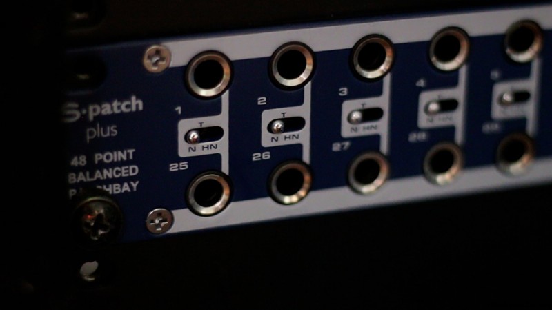
Piense en cada par de conectores verticales en su patchbay como un módulo. Hay tres modos generales y el modo que elija determinará cómo funcionará ese módulo.
Modo directo
El primer modo, y el más básico, es el modo 'Thru'. Esto significa que el conector superior en la parte trasera simplemente fluirá hacia el conector superior en el frente y el conector inferior en el frente simplemente fluirá hacia la fila inferior en la parte posterior. En este modo, los conectores superior e inferior funcionan de forma independiente.

Medio normalizado
El segundo modo se llama medio normal. En el modo medio normal, las tomas de la parte posterior siguen correspondiendo a las tomas de la parte delantera (al igual que en el modo 'Thru'), pero la señal de la toma superior fluirá automáticamente hacia la toma inferior de manera predeterminada cuando no haya cable de conexión. está conectado. En el modo medio normalizado, esta conexión predeterminada se interrumpe cuando conecta algo al conector inferior del panel frontal. En otras palabras, el conector de salida en la parte superior fluye hacia el conector de entrada en la parte inferior a menos que haya algo más conectado a ese conector de entrada.

Normalizado
El tercer modo se llama completamente normal. En el modo totalmente normal, la conexión predeterminada de arriba a abajo se interrumpirá cuando se conecte un cable al conector superior o inferior del panel frontal. So, connecting a patch cable to the output or the input jack will break the default connection.

Patchbay Layout
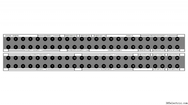
There are lots of uses for each of these modes and the possibilities are endless, but here are some examples of how I have set up my patchbay to meet the needs of the various devices in my studio.

The top left corner of my patchbay is where my microphones come in. Some of my microphones (like this boom mic) are directly wired into the top row of jacks on the back of my patchbay. Alternatively, I could have an XLR panel in the back of the room that connects to the top row of jacks on the back of the patchbay. That way, I could connect a microphone to that XLR panel which would then be available on the top row of my patchbay.
I will almost always want my microphones to connect to the microphone preamps on my audio interface, so I’ve set these jacks up in full-normal mode. This means the mics will be connected to my interface by default without any patching. But if I want to patch the microphone to a different mic preamp I can simply do so with a patch cable.
I chose to use full-normal instead of half-normal, because I don’t want to accidentally connect my microphone to two preamps that are both supplying phantom power. When I connect a patch cable to the top jack, it automatically breaks the connection to my interface. This also prevents me from connecting two microphones to the same audio interface preamp.
The other essential connections for my typical workflow are set up using half-normal mode. For example, my interface outputs flow directly to the input of my monitors. If I want to patch my turntable directly into my monitors for a pure analog connection, I can patch from my phono output jacks to the monitor input jacks and bypass the other components of the system. Given that this is set up in half-normal mode, the default connection from the interface outputs will be broken when I connect to the monitor input jacks.
Half-normal jacks also provide a way to split a signal. Let’s say I want to send my interface output to the input of my monitors while also sending that output to my wireless headphones. I just patch the output of my interface to the input of my wireless headphone transmitter and the signal still flows down to the speakers, because nothing is connected to the bottom jack. Remember – in half-normal mode, the connection is only broken when there is a plug in the bottom jack.
I use ‘Thru’ mode for my outboard effects and preamps because I don’t want the outputs of my compressor or outboard preamps to feed into their own inputs and create a feedback loop. Setting these modules to ‘Thru’ mode keeps the top jack and bottom jack independent from one another, meaning I need to manually patch these devices anytime I want to use them.
Which Patchbay Should You Use?
I have two 48-point ¼-inch TRS patchbays. One is a Neutrik, which costs about $100. The other is a Samson S-Patch Plus, which is a little more expensive. I’ve had some time to compare these two options and I think the Samson is well worth the extra money.
If I want to change the mode on any module in the Samson S-Patch Plus, I just need to toggle the switch between the top and bottom jack.

In order to switch the mode on one of the Neutrik modules, I need to disconnect the jacks from the front and back, remove the front panel of the entire patchbay, take the module out, flip it around, and reassemble everything.
This has caused me a few headaches as I have continued to add components and shift things around on the patchbays, so I would definitely recommend going with the Samson S-Patch Plus if you’re on the fence.
You should also consider how much space you have and how many connections you’ll need. These two 48-port patchbays take up 1RU of rack space each, which can really add up…
If you’ve got a larger collection of components or less rack space to work with, you may want to look into a TT (or tiny telephone connector) patchbay instead. These will be more space efficient, as the density of connection points is much greater with these smaller connectors.
You will also find patchbays that have multi-channel connectors in the rear rather than the same connection type on front and back. This can make for a cleaner setup, utilizing multi-channel fanouts rather than an individual cable on the rear panel for each connection.
- ·Cómo configurar un reproductor de MP4
- ·Cómo instalar un sistema de PA
- ·Cómo configurar un ecualizador Sound System
- ·¿Cómo instalar un receptor Yamaha a Cable & HDTV
- ·¿Cómo puedo configurar un receptor AV
- ·Cómo configurar un 2 canales para DJ
- ·Cómo configurar un micrófono de estudio
- ·Cómo configurar XM RADIO
